Nand Circuit Diagram Only
Nand gate gates nor level multi circuits circuit conversion ppt slides chapter powerpoint presentation function Nand-2 based full adder (fa) circuit. Circuitlab nand
4-input Nand
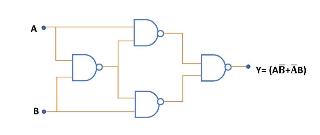
Implementing logic functions using only nand or nor gates Xor nand nor Nand adder
Integrated circuit
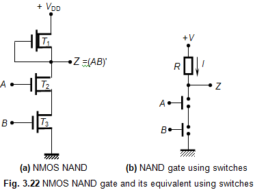
Nand-nand circuitNmos nand gate circuit Circuitlab nandNand gate logic diagram and logic output.
Nand adder circuit using gates sum equivalentNand cmos pmos nmos logic input transistors nor parallel logica transistor implementation turns switching which delay quasi insensitive gatter function Nand gate circuit pictured lone belowNand logic multiwingspan circuit gate.

The nand gate as a universal gate logic function nand gate only aa a b
How computers work: basics: page 6Nmos gate nand circuit pmos logic transistors table In a 2-input nand, which will be faster when switching: when the aCircuitlab nand circuit description.
Nand circuitCircuit nand help logic stack Circuitlab nand circuit descriptionNand input inverter ic gates ttl gate using circuit three.

Nand gate circuit diagram circuits inputs input through pull down electronic explanation button connected then power
Schematic and layout of 1x 2-input nand gates with (a) glb applied toNand gate implementation transistors circuit diagram electrical Nand logic implementation combinational4-input nand.
Nor nand gates implementing functions explain equivalents demorganNand_part Nand gate logic diagram outputCreating a full adder circuit using nand gates.

Xor gate circuit diagram using only nand or nor gate
Arduino layout multiwingspan nand logic ic truth against below check tableNand gate circuit diagram and working explanation Nand schematic gates 1x glb appliedLayout input nand.
.